CABLE AND HARNESS
SOLDER SLEEVES
solder sleeves
SOLDER SLEEVES

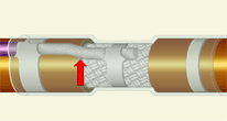
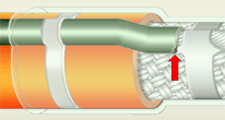
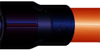
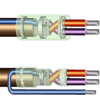
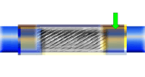
Solder sleeves are primarily used to attach a ground wire (lead) to the shielding braid of a shielded cable by means of a shrinkable tubing assembly having an integral solder preform.

Solder sleeves are also used to splice two or more conductors together in a parallel configuration.

See Section 4.01 "Cable and Harness, General Requirements", and Section 6.01 "Through-Hole Soldering, General Requirements", for common accept/reject criteria.
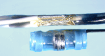
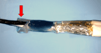
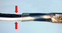
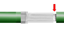
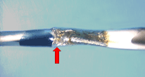
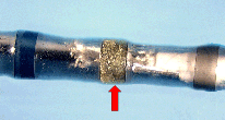
properly installed solder sleeve termination exhibiting proper solder flow

PREFERRED

Solder sleeve has been properly installed and tightly shrunk. Strain relief is acceptable. Overlaps are of sufficient length to meet minimum electrical spacing. Solder fillet is visible, fully flowed and smooth.

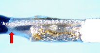
ACCEPTABLE

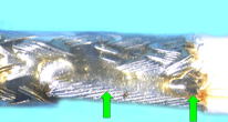
CLOSE-UP VIEW

The termination exhibits proper solder flow and complete wetting. There is evidence of a complete fillet between the ground wire and the shield. Individual strands are discernable. Minor flux entrapment is acceptable.

NASA-STD-8739.4 [19.6.1.b], [19.6.1.g]
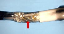
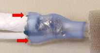
solder sleeve with discoloration damaged sleeve

ACCEPTABLE

DISCOLORATION

The solder sleeve may exhibit slight discoloration resulting from the heating process. The sleeve shall not exhibit any damage.

NASA-STD-8739.4 [19.6.1.g.3]

UNACCEPTABLE

DAMAGED SLEEVE

Solder sleeves shall be free of cracks, cuts, crushing, gouges, punctures and charred, melted or burned areas. Slight scuffing or discoloration is acceptable.

NASA-STD-8739.4 [19.6.1.g.3], [19.6.2.g.6]

NASA WORKMANSHIP STANDARDS
NASA logo Released:
04.05.2002
Revision:
Revision Date:
Book:
4
Section:
4.06
Page:
1


CABLE AND HARNESS
SOLDER SLEEVES (cont.)
damaged wire insulation excessive conductor length

UNACCEPTABLE

DAMAGED WIRE INSULATION

Cut, crushed, gouged, damaged, nicked, burned or melted insulation may result in reduced electrical isolation and/or short circuits. Slight scuffing or discoloration is acceptable.

NASA-STD-8739.4 [19.6.2.e.9]

UNACCEPTABLE

EXCESSIVE CONDUCTOR LENGTH

The ground conductor should extend a maximum of flush with the end of the stripped shield section.

Best Workmanship Practice

excessive insulation clearance exposed conductive surfaces

UNACCEPTABLE

EXCESSIVE INSULATION CLEARANCE

The maximum insulation clearance shall be such that the end of the conductor insulation is even with the end of the cable jacket.

Best Workmanship Practice

UNACCEPTABLE

EXPOSED CONDUCTIVE SURFACES

Solder sleeves shall cover all exposed metal in the splice area. Improper positioning, movement during shrinkage or improper sizing of the sleeve, typically results in exposed conductive surfaces.

NASA-STD-8739.4 [19.6.2.g.5]

improper location incomplete fillet

UNACCEPTABLE

IMPROPER LOCATION

Solder sleeves should be installed, such that the solder preform is approximately centered on the stripped section of the conductors, ensuring proper sealing and strain relief.

Best Workmanship Practice

UNACCEPTABLE

INCOMPLETE FILLET

The termination shall exhibit a complete, fully wetted fillet along both sides of the interface between the two conductors.

NASA-STD-8739.4 [19.6.2.g.2], [19.6.2.g.3]

NASA WORKMANSHIP STANDARDS
NASA logo Released:
04.05.2002
Revision:
Revision Date:
Book:
4
Section:
4.06
Page:
2


CABLE AND HARNESS
SOLDER SLEEVES (cont.)
incomplete shrinkage of solder sleeve incomplete solder flow

UNACCEPTABLE

IMCOMPLETE SHRINKAGE

The solder sleeve shall be completely shrunk to provide a tight fit and proper stress relief.

NASA-STD-8739.4 [9.10], [11.4], [19.6.1.b.6]

UNACCEPTABLE

INCOMPLETE SOLDER FLOW

The solder preform has not melted and properly flowed. Typically this is caused by insufficient heat, insufficent dwell time during the shrinkage process, or use of an infra-red (IR) heat source.

NASA-STD-8739.4 [19.6.2.g]

insufficient insulation clearance separated shield strands

UNACCEPTABLE

INSUFFICIENT INSULATION CLEARANCE

The insulation shall not be imbedded in the solder joint. The contour of the conductor shall not be obscured at the termination end of the insulation.

NASA-STD-8739.4 [10.1.7.a.1]

UNACCEPTABLE

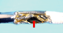
SEPARATED SHIELD STRANDS

Birdcaged or separation of the shield stranding may introduce unwanted electrical noise into the system, and may interfere with the proper installation of the solder sleeve.

NASA-STD-8739.4 [19.6.1.e.16]

protruding strands termination not visible

UNACCEPTABLE

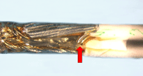
SEVERED/PROTRUDING STRANDS

Conductors exhibiting severed strands shall not be used. Severed wire strands may protrude through the solder sleeve, creating a shorting and reliability risk.

NASA-STD-8739.3 [7.2.3]
NASA-STD-8739.4 [19.6.2.a.2], [19.6.2.g.7]

UNACCEPTABLE

TERMINATION NOT VISIBLE

The solder sleeve is opaque, prohibiting visual inspection of the termination. The solder sleeve shall be transparent or translucent to allow inspection.

NASA-STD-8739.4 [19.6.2.g.1]

NASA WORKMANSHIP STANDARDS
NASA logo Released:
04.05.2002
Revision:
Revision Date:
Book:
4
Section:
4.06
Page:
3


Click here for printable .pdf file for Section 406 Cable and Harness Solder Sleeves click here to download Adobe Reader Click here to email the author of the Pictorial Reference Handbook
Need a printed copy?
(May take a while to load.)

Requires Adobe Reader.
Need Adobe Reader?
Click here to download.
Questions? Suggestions?